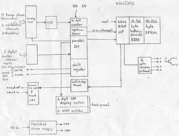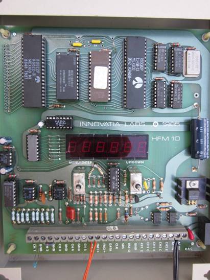

The DAS201 MiniDAS is a single-board DAQ with the following block diagram (MAY16).


The 5 input channels are designed for precision
interchangeable thermistors (0-105 degC) but can instead be voltage inputs
of 0 V to 4 V fs.
The two digital inputs can detect switch closures or more
generally be bit inputs.
The serial synchronous two-bit interface extends the I/O of
the DAQ.
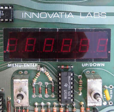
The user output is 6 7-segment LEDs.
The user input is a 4-button switch-mouse: MENU (or ESC), ENTER, UP, and DOWN for traversing menu trees and numeric entry.

A jumperable watchdog timer circuit drives the /NMI input of
the 6502 mP.
A reset IC initiatess the mP
reset computing thread at power-on.
Input power is 6.3 V rms from which is generated 5 V and -5
V.
Two optionally optoisolated output bits - for datalogging or
control.
Data acquisition is through an 8 channel MUX followed by a
VFC that drives the mC counter input.
The VFC IC (an LM331) and op-amp output a buffered reference
voltage, VR = 4.0 V for ratiometric input dividers.
Two of the 8 channels have precision 1/4 and 3/4 dividers
with 0.1 % resistors from VR for two-point calibration.
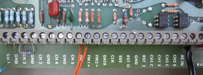
All connections are along one terminal strip along the bottom side of the circuit-board.

![]()
![]()