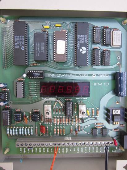

The Innovatia DFC601 Dual Fan Controller controls temperature by controlling ventilation fans. It has up to 4 temperature sensor inputs and two air-flow sensor inputs. It has outputs for controlling up to two independent fan systems. It is a single-board microcomputer-based controller. The prototype is shown below.

All connections to the unit are made at the single terminal strip at the bottom of the board. All user interactions with the unit are made through the 6-digit 7-segment display and 4 momentary-contact pushbuttons labeled MENU (or Escape), and Enter, on the left switch pair and Up, and Down on the right switch-pair.
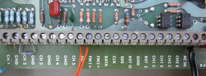
The terminal strip is shown in detail below.

The connections for the DFC601 are as follows:
|
Number |
Name |
Description |
|
1 |
CH1 |
Fan 1 indoor thermistor temperature sensor |
|
2, 4, 6, 8 |
GND |
Adjacent connections to second wire of temperature sensor |
|
3 |
CH2 |
Fan 1 outdoor thermistor temperature sensor |
|
5 |
CH3 |
Fan 2 indoor thermistor temperature sensor |
|
7 |
CH4 |
Fan 2 outdoor thermistor temperature sensor |
|
10 |
FM– |
Air-flow sensor common connection |
|
11 |
FM1+ |
Fan 1 air-flow sensor |
|
12 |
FM2+ |
Fan 2 air-flow sensor |
|
17 |
GND |
Reset pushbutton ground connection |
|
18 |
RST I |
Reset pushbutton input connection (optional) |
|
19 |
CH1 C |
Fan 1 on-off control output |
|
20 |
CH1 E |
Fan 1 on-off control output |
|
21 |
CH2 C |
Fan 2 on-off control output |
|
22 |
CH2 E |
Fan 2 on-off control output |
|
23, 24 |
AC IN |
9 V ac rms input |
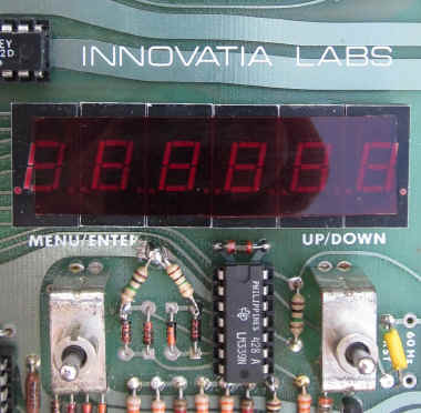
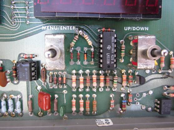
The DFC601 is operated through its “front-panel” user interface, shown in detail below.

Below the 6-digit LED display are two pairs of switches. Each switch lever can be pressed upward or downward. For the left switch-pair, pressing upward selects the MENU or Escape. Pressing down, selects Enter. The right switch-pair, when pressed upward, selects UP and when pressed downward selects DOWN.

These four switch positions operate like a computer mouse. UP and DOWN are like rolling the mouse to select a menu item or change a numeric entry. ENTER (left mouse button) enters a menu item or enters a number on the display. MENU (right button) escapes from the selected menu item.
When the unit powers on or is reset, it shows the first item in the menu: temp 1. On the seven-segment display, some letters are limited in their formation. An “m” is formed from two digits with an “n” in the leftmost digit. The list of menu items, in order with their descriptions, is given in the following table.
To scroll through the menu items, press the UP and DOWN switches. Each press advances to the next item, in either direction. If UP is pressed, the menu can be scrolled in the reverse direction by pressing DOWN. When the desired menu item is displayed, press ENTER. For some items, the display will continue to show it until the MENU (Escape) switch is pressed, returning the display to the menu list.
|
Display Item |
Description |
|
temp 1 |
Display indoor (left) and outdoor (right) temperatures of fan 1 system. |
|
temp 2 |
Display indoor (left) and outdoor (right) temperatures of fan 2 system. |
|
fan 1 |
Select fan 1. |
|
fan 2 |
Select fan 2. |
|
on |
Turn selected fan on and override fan control. |
|
off |
Turn selected fan off and override fan control. |
|
Low t |
Set the low temperature threshold for the controller. |
|
High t |
Set the high temperature threshold for the controller. |
|
Lo dt |
Set the temperature difference between the low threshold (fan off) and outdoor temperature. |
|
Hi dt |
Set the temperature difference between the high threshold (fan on) and outdoor temperature. |
|
deg F |
Display and enter temperatures in degrees Fahrenheit. |
|
deg C |
Display and enter temperatures in degrees Celsius. |
|
FLOW |
Display air-flow sensor reading for selected fan. |
|
reset |
Reset controller; same as powering on unit. |
|
cntrl |
Activate fan temperature control using indoor temperature sensor only. |
|
dcntrl |
Activate fan temperature differential control using indoor and outdoor temperature difference. |
The temp 1 or 2 item, when selected, shows the indoor temperature on the left and the outdoor temperature on the right in either degrees F or C. The default unit is F which is set at power-on or reset. This display is a useful one to leave the controller in for hands-off monitoring of the temperatures of either fan system. It is useful for reading the indoor and outdoor temperatures.
Fan 1 or fan 2 can be controlled manually by invoking either the fan 1 or fan 2 menu items. When entered, the chosen fan will be selected and the menu will advance to the on item for convenience. By entering on, the selected fan is turned on and stays on. By pressing the DOWN switch from the on menu item, the off item can be selected and entered instead, turning the selected fan off to stay off. Fans can thereby be controlled manually.
The high t and low t menu items are used to set the high and low indoor temperatures between which the controller will cycle for indoor temperature control. They are entered in the temperature units selected. The (unselected) default unit is °F. To set the high temperature for either fan system, select fan 1 or 2 on the menu and enter. Then select the menu item high t and enter. Similarly, to set the low temperature, enter low t and set it. The low temperature value is not allowed to exceed the high temperature value. Press the UP and DOWN switches to enter the desired temperature to a tenth of a degree. As the switch is held in either the UP or DOWN position, the change in the displayed number accelerates. As the desired number approaches, release the switch, then press it again to more slowly approach the final value. If overshot, press the switch of opposite direction. When the display shows the desired temperature, press the enter switch to enter it. If the initial temperature is desired and the changes are to be ignored, press MENU to escape to the menu without changing the high or low temperature setting.
The indoor-sensor control uses the high and low temperature settings of the previous menu items. In differential control, Lo dt and Hi dt settings are the differences in temperature between the outdoor temperature and the temperature at which the fan turns on (Hi dt) or off (Lo dt).
Suppose the outdoor temperature is a cool 65 °F and you want to turn the fan on when the indoor temperature rises 9.0 °F above the outdoor temperature. Then Hi dt is set to 9.0 in Fahrenheit units. This is also the default value at reset. Then when the fan turns on, bringing in cool outside air, the indoor temperature drops. The Lo dt setting turns off the fan when it is the Lo dt temperature above the outdoor temperature. Suppose (as is the default value) that Lo dt is set to 4.5 °F. Then when the indoor temperature is reduced to 4.5 °F above the outdoor temperature, the fan turns off. If the Lo dt setting is too low and the fan system is not able to reduce the indoor temperature to it, the fan will remain on continually. By increasing Lo dt, a number of degrees above the outdoor temperature can be set that allows the fan to turn off after an acceptable amount of time. If Hi dt is set too high, the fan might never turn on. Adjust the Hi dt and Lo dt settings until satisfactory fan performance results. The one- and two-sensor control schemes are illustrated below.
The default power-on or reset temperature unit is degree Fahrenheit (F). If Celsius units are desired instead, select the menu item deg C and enter. To change back to F, select deg F and enter. Both display and settings input are in the selected unit.
The fan 1 or 2 air-flow sensor readings can be displayed by selecting the FLOW menu item. The count displayed is an indication of the speed that the sensor blade is turning in the fan air-flow. A zero reading indicates that the fan air-flow is low or has ceased. The display of air-flow is for the previously selected fan., At power-on or reset, no fan is selected and the flow reading is zero.
The optional reset item displayed as reset, when entered, returns the controller to the same state as when powered on, including the default factory settings for high and low temperatures of 82.4 °F (28 °C) for the high temperature and 77 °F (25 °C) for the low temperature setting. The Fahrenheit unit is set and control is turned on. After these defaults, reset then displays the resistance, in ohms, of the channel 2 sensor. This is used for diagnosing sensor-related problems.
Both fan 1 and 2 systems have their own independent control and both are either under indoor-temperature (absolute) control or both under differential-temperature control relative to the outdoor temperature. If the displayed item cntrl is entered, absolute control is turned on. If indoor temperature (channel 1 for fan 1 and channel 3 for fan 2) is above the high-t setting, the fan is turned on until the indoor temperature decreases to below the low-t setting and the fan is turned off. Thus, the temperature cycles between the high and low temperature settings.
If the menu item displayed as dcntrl is entered, differential control is turned on. It operates on temperature difference instead of absolute temperature according to the following procedure:
If indoor temperature > (outdoor temperature + lo dt) then fan turns on
If indoor temperature < (outdoor temperature + hi dt) then fan turns off
As the indoor temperature rises above the cool outdoor temperature, the temperature difference will exceed the hi dt temperature setting until it is at the outdoor temperature plus hi dt. This will turn the fan on until the difference comes down to that of the lo dt temperature setting. Then the fan turns off.
![]()