
The Huron is a low-cost data acquisition and control system for remote, stand-alone or embedded-system applications. It acquires data from pressure, flow, temperature, force, digital and acceleration sensors, drives PCM servomotors and high-current digital outputs, records I/O channels, telemeters data, and provides a versatile application-programming environment. The RS-232/RS-485 serial port networks Hurons and supports long-haul communications. The Huron has extensive fault recovery and restart capability.
·
Remote
data acquisition & control
·
Test-stand
instrumentation
·
Vehicle
monitoring subsystem
·
Automated
machine control
·
Sounding
rocket flight controller
·
Programmable
acquisition sequencing
·
12
bit A/D conversion
·
16
analog input channels
·
Programmable
input ranges: 4 mV to 4 V
·
Wide
range of sensor types
·
Power-fail
and software dethread recovery Battery-backed 32 kbyte data recorder
·
Small-area,
large-geometry computer
·
Serial-port
remote control: RS-232 or RS-485 networking
·
Configurable
telemetry frame
·
Single
board with optional enclosure
·
Affordable
price
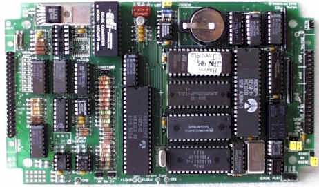
The Huron is a single-board, microcontroller-based data acquisition and control system.
Microcomputer: 8-bit 6502 microprocessor, 1 MHz clock, standard; 32 kbytes battery-backed RAM; Battery: CR2032
Telemetry encoding: sent via RS-232 or RS-485 serial port; ASCII text data viewable and in spreadsheet format.
Serial port: 3-wire RS-232 (RXD, TXD, GND) or RS-485 (+data, -data, gnd), 1200 to 19,200 baud, xon/xoff protocol.
Input/Output: The Huron has 25 I/O channels.
Sampling resolution: 12-bits; 1 mV/count.
Sampling inaccuracy: 12 bits ± 1 LSB (±0.05 %), with two-point calibration; ± 1 % uncalibrated.
Sampling rate: £ 200Hz (5 ms) total, for all channels.
Input range: ± 4 V full-scale.
Programmable-gain amplifier voltage gain: 1 to 1000 in decades; full-scale inputs: ± 4 mV to ± 4 V in decades.
Bridge-supply voltage source: 4.1 V ±3 %,
£
500 mA.
Eight general-purpose differential analog inputs can accept direct connection to bridge-based sensors.
Voltage input range: ± 4 Vrange.
Thermocouple:
type K thermocouple; type J optional; field-replaceable integrated circuit:
AD594 (J), AD595 (K).
Volts 0, Volts 1: differential ± 4 V (´1 gain), 30 V common-mode range; for high-side current or power bus/battery voltage measurements.
Vbr:
The bridge supply voltage; supplies AIN-
input for half-bridge sensors at Vbr/2, and is used for compensation of bridge voltage
measurements.
Digital Inputs (DINP): 8 TTL-level, closure-to-ground bit-inputs, with 33 kW pull-up resistors; 8 additional external inputs via the serial I/O bus.
Flow 0, Flow 1: digital pulse inputs, 50 mV pk-pk, £ 200Hz each channel: hysteretic inputs; for magnetic-vane or contact flow sensors. Jumpered 1 MW pull-up resistors for switch-closure (to ground) flow sensors.
Thermocouple open fault: open thermocouple sensor circuit fault detection.
Frequency: TTL-level, 20 Hz to 500 kHz; for frequency-to-quantity conversions by serial-bus analog acquisition; 50 ms count interval.
Digital Outputs (DOUT): 7 bit-outputs sink 250 mA of current each when on, with 33 kW pull-up resistors; not protected from overcurrent or overvoltage; 8 additional external TTL-level outputs via the serial I/O bus.
Relay: 3 A; COM, NO and NC contacts.
PG0, PG1 pulse generators: TTL-compatible logic levels.
PCM0, PCM1: PCM outputs for driving 5 V RC (radio-control) servomotors: 1 ms pulse width for -fs; 2 ms for +fs; 1.5 ms zero-scale.
Synchronous serial TTL-level I/O on 6 lines: data input, data output, clock, input strobe, output strobe and ground; provides additional 8 input and 8 output digital lines for the DINP and DOUT channels.
All connectors are 0.1 inch square-pin: 40-pin ANALOG and DIGITAL IDCs, 4-pin POWER, 3-pin serial port, 2-pin RESET and 2-pin WARMSTART; WDT jumper.
5 V @ 0.5 A; ±12 V @ 50 mA + bridge current from +12 V supply. Bridge current £ 0.5 A, with heat sinking.
7.15 ´ 4.15 inch circuit board, with mounting holes for a Polycase DC47 enclosure.
Ambient temperature: -40 to +70 deg C.
Relative Humidity: noncondensing.
Innovatia Microcontroller Programming Environment & Language; Forth-83 based interpreter and incremental compiler; floating-point and high-level I/O support. Highly refined, reliable code, in use in multiple products.
Set and clear digital bits, measure flow rates, frequency, raw and processed analog data; pulse generators and relay; set PCM channels, in ± 100 % range.
Clear and configure telemetry frame by setting channel sampling rate and offset into frame. Unschedule channels and output % of acquisition bandwidth used.
Set channels to default or selected units, set channel gain (fs value), transducer type (linear, linear bridge, J or K type thermocouple, 100 W RTD, 1 kW RTD, AD22100 silicon temperature sensor, digital, or user-defined. Set channels to default or selected processing functions, assign bridge-supply measurement channel; output resistance (multichannel ohmmeter); calibrate channel for transducer type; output calibration parameters.
Erase, turn recording on or off, playback and output % of recorder memory filled and recording time for given frame. Playback function outputs data in telemetry subframe format:
CR time channel channel-name data-value unit
for spreadsheet capture or display. Modify format by turning channel name and unit off.
Clear and set telemetry channels, turn telemetering on/off, and telemeter next subframe.
Set time, in 0.1 s units and output time. Clock time is output in telemetry subframes.
Default configure channels; output Huron configuration table; assign restart routine (word) recovery word in case of power-fail or power-on reset; enable/disable and reset interrupted-level software watchdog timer; initialize RS-485 network mode; initialize node number; send line of text to node n.
Computer resets are: cold start forgets downloaded program, retains configuration; warm start returns to interpreter; and restart runs the designated recovery routine upon hardware reset or watchdog timer timeout. Program on-board missions in IMPEL; modify downloadable template programs. Program in user language on system computer to send Huron commands and receive results over serial-port link.
2NOV98
![]()
![]()
![]()
![]()
![]()