Prototype LCS201, based on the DAS201 MiniDAS. The 4-pin connector at
upper-right interfaces to the dot-matrix LED display..
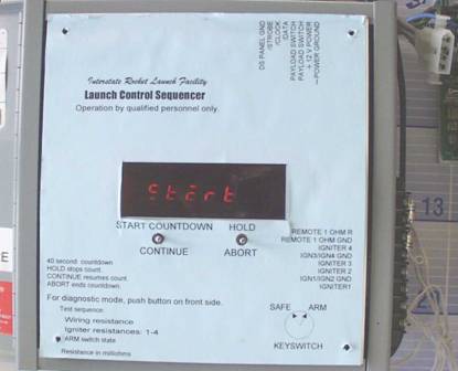
The LCS201 has four igniter circuits and can simultaneously ground-start up to 4 engines. When the "Start Countdown" switch is pressed, the count starts at -40 seconds on the display. At -35, "Start Launch" is displayed, and "All Go" appears a few seconds later. Then at -10 seconds, the payload relay closes, activating on-board rocket electronics. By switching on the rocket electronics at this time, the on-board battery remains charged and possible failure due to delays is avoided. At 0 seconds, "IGNITE!" is displayed and ignition occurs. If the Arm switch is not in the armed state, the message instead is "No Arm" and ignition does not occur. Upon ignition, the countdown continues with positive seconds, and the operator can then press the hold switch at touchdown to measure the time of flight. During flight, other events such as burnout or parachute ejection can be timed by reading the time on the display when they occur.
During countdown, unexpected incidents may require that the count be put on hold. The "Hold" switch stops the countdown at the time the switch is pressed. When the problem is resolved, the count is continued by pressing the "Continue" switch. If the countdown needs to be aborted, the "Abort" switch returns the controller to the start state.
The LCS201 also contains built-in electrical system diagnostics which are used to verify that the igniter circuits are wired correctly. A fifth switch starts the test-mode sequence, which measures the resistance of each of the four igniter channels. Igniters typically have a resistance of 1 to 2 ohms, but if the circuit is open, the display shows "Open." The readings are in milliohms (mW); a reading of 1000 is one ohm. Shorts can also be detected by unusually low resistance readings. The last test in the sequence checks the arm-switch state (which is either armed or safe).
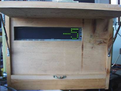
The LED dot-matrix prototype display, driven by the launch controller,
shows the count at T minus five seconds.
Because the wire running to the igniter can be long and have appreciable resistance, the wire resistance is automatically calibrated out of the igniter measurements by placing a reference 1 W resistor on a wire pair at the launch stand. This reference channel is used to auto-calibrate the LCS ohmmeter.
The normal operating procedure is to connect the ignition circuits to the rocket and then run the test sequence, noting the resistance of each igniter and the state of the arm switch (which should be "no arm"). If the igniter circuits check out okay, then the arm switch is set to the armed position and "Start Countdown" is then pressed. Testing the igniter circuits will not fire the igniters; the test current is far too small.
The LCS201 microcontroller operates the front-panel, ohmmeter, and firing circuits. The board is attached to the back of the front-panel, to form a module. A single connector strip on the controller board takes in 5 V power, has outputs to drive the ignition and payload relays, reset switch input, the four-wire dot-matrix display interface, switches, and the five resistance channels (4 igniters plus 1W reference).
The microcomputer (mC) consists of a 6502 microprocessor, 8 kbyte EPROM (2764), 2 kbyte RAM (6116), clock generator, reset IC, address decoding, and the I/O chip, a 6522 VIA. The on-board front-panel is driven by a CA3082 NPN transistor array and a 74LS145 decoder. The mC sequences the decoder through the seven segments plus decimal-point and turns on the displays using that segment for the given message. A display is turned on by driving its CA3082 transistor base high, which asserts the common anode pin.
The on-board switches are two up-down toggle switches, having four momentary-contact switch functions. These switches are multiplexed on two 6522 input pins using the display decoder sequencing.
For output relay interfacing, a dual flip-flop latches the ignition and payload relay states and drives open-collector transistors which interface to off-board relays. Additional buffers and a MMV pulse stretcher drive the dot-matrix display connector pins.
The ohmmeter is implemented with an analog multiplexer (4051), dual op-amp (LF353), and voltage-to-frequency converter (LM331). The frequency is counted by a VIA counter for an accurate time interval, to determine frequency. The LM331 has a voltage reference (pin 2) that is buffered by one of the LF353 op-amps to provide a 1.9 V source. This source drives accurate (0.1 %) resistors that form a voltage divider with the igniters. One of the voltages of the 5 channels is selected by the multiplexer, amplified 100 times by the other op-amp, and applied to the LM331 input.
The ohmmeter is calibrated by mC software that makes measurements at 1/4 and 3/4 the reference voltage, provided by accurate voltage dividers. A line is drawn through the two points algebraically, and the slope and offset are found. These calibration parameters are then used to correct resistance readings.
![]()
![]()
![]()
![]()