
Instead of using a hysteresis brake for the motor load, we are using a 1 kW brush motor interfaced to a commercial motor-drive with regenerative braking. The drive input will be a microcomputer that will close either a commanded speed or torque loop and also drive the front-panel and serial port - the two operator interfaces.
The technical overview of the project is given below.
Build Your Own Dynamometer
the Basic Motor Control Instrument
A dynamometer is a basic mechanical instrument used in the development of motors and motor drives. A "dyno" is a controlled, mechanical, rotational load. It controls either speed or torque and measures both. With a dyno, the torque-speed curves of motors can be plotted, and their motor-drives can be tested over the intended operating range. Dynos are to motors and motor drives as oscilloscopes are to electronics – a basic test instrument.
Rotational speed is usually measured with a shaft encoder, and torque with a torque sensor. The load is usually a brake or a generator. A brake is an active electromechanical device. Its resistance to rotation is controlled by a small field current. For smaller dynos, total mechanical power loss in the load can be tolerable. These hysteresis brakes are found on dynos of leading suppliers, such as Magtrol and Vibrac.
Build Your Own Dyno
A typical bench-top dyno costs $10,000 or more. The corresponding electronics test instrument, the digital storage oscilloscope, can be bought for around $1,000, a rather sizeable difference. Consequently, for small laboratories on limited budgets, it can make sense to build a dyno, especially if the project keeps technicians busy between other tasks.
A more elegant approach than a brake is to regenerate, not dissipate, load power using a generator. Generated electric power can be inverted and fed back into the power line, completing the circuit of power back to the motor-drive under test. The only losses are conversion losses in the test set-up. More simply, though less efficiently, it can be dissipated in a resistor bank.
Motors are also generators. Brush motors are being replaced with PMS motors and are relatively low-cost on the surplus market. PMS motors can also be used. Not only can the motor (used as a generator) provide loading, when calibrated, its output current can be a measure of load torque. This eliminates having to buy an expensive torque sensor.
The basic dyno scheme is shown below.
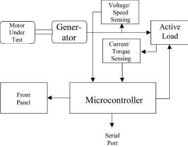
The motor-drive connected to the load generator must have regenerative capability, and to be fully regenerative, it must also have an inverter supply that can convert power from the generator into grid-compatible ac. This is half the problem. The other half is measurement and control. A simple shaft encoder can detect speed digitally, using an optical path or Hall-effect device. The torque sensor can be the regenerative load motor, once calibrated. Sensors are then interfaced to a microcomputer, which also drives a serial port, for computer control, and an optional user front-panel.
The scheme can be simplified further by eliminating the speed sensor and sensing speed from the generator induced-voltage frequency. For slow speeds, this voltage can become small. To achieve a constant-amplitude output at all speeds, the induced voltage is input to an op-amp integrator. The output will be reliable down to very slow speeds, and can be input to a comparator and on to the microcontroller counter.
![]()
![]()
![]()