
Vector-Summed Control - an innovative breakthrough in 6-step PMS motor-drives
A simple, low-cost approach to phase control of three-phase synchronous permanent-magnet motors results from straightforward application of vector-based motor theory. It vectorially sums the induced voltage waveforms of motor windings and uses their zero-crossings to produce correctly-phased six-step commutation.
|
For years, the search has gone on for a simple,
winding-sensed ("sensorless") six-step control scheme for three-phase,
brushless, permanent-magnet motors. | |
|
Most schemes are "Rube Goldbergs"
that use an excessive number of components and work over a limited speed range.
By starting with vector (and not steady-state phasor) motor theory, a simple,
elegant scheme has been worked out, called vector-summed phase control. | |
|
The open (undriven) terminal of a
three-phase motor is sensed and the voltage on it used in a new and
different way to determine precisely when to switch to the next phase step. | |
|
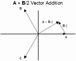
Because the open phase-winding zero-crossings occur in the middle of drive-steps, they cannot be used directly to advance phase. This phase-offset problem is solved by a vector reconstruction technique that follows from vector-based motor theory. Instead of sensing open-winding zero-crossings, a voltage is instead synthesized according to the formula: |
![]()

This results in a vector which crosses zero at the phase-step transitions and can be used to commutate the motor.
| Vector-summed control works equally well with Y- or D-configured windings. |
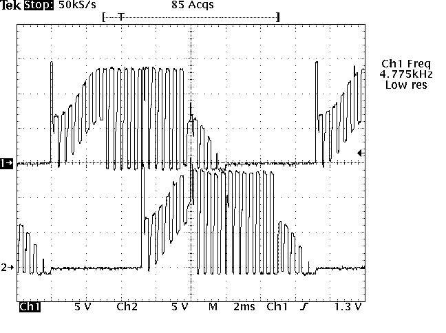
Vector-summed commutation has been tested with both winding configurations. The results for a delta-configured motor (below) show waveforms at two motor terminals.

The drive intervals (steps) for both waveforms are centered around the peaks, indicating good phase alignment. This centering remains constant over a wide motor speed and load range.
While either terminal is open, the induced-voltage vector sum of the phase-windings connected to it results in an induced-voltage waveform with the PWM drive waveform superimposed upon it. In trace 1, the rising waveform shape is evident during the second through first half of the third division, and the sixth division.
Around the peaks of each half-cycle, the terminal is driven, in trace 1 during the last half of the third through the fifth division. During the drive interval, the full amplitude of the PWM waveform appears, and is flat on top, at the voltage of the motor drive voltage.
Similar results were obtained with the Y configuration. While the motor was running, the neutral-node connection was switched between the physical motor neutral terminal and a virtual neutral node. No difference in behavior was observed, electrically or mechanically.
Reference paper: "Synchronous Motor Phase Control by Vector Addition of Induced Winding Voltages", D. Simon, D. L. Feucht, IEEE Transactions on Industrial Electronics, June 2004, Vol 51, No. 3, ITIED6, pp. 537 ff.
![]()