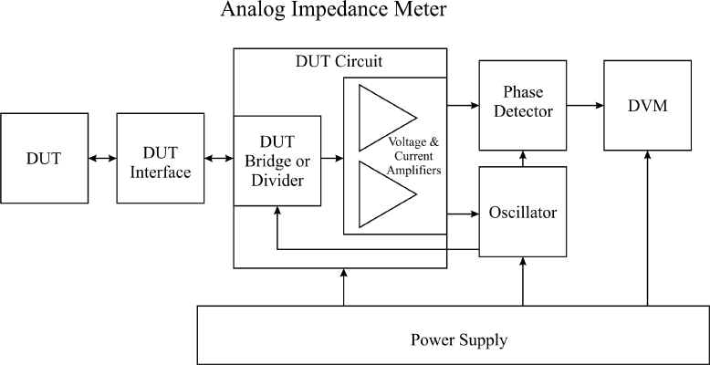
Impedance Meters and Analyzers
Impedance meters (ZMs) or RLC meters measure resistance and reactance of two-terminal devices. Measurement is made by driving the device under test (DUT) with a sine-wave voltage or current and measuring the resulting current or voltage. Then a microcontroller computes the resistance or reactance resulting in a displayed value of R, L, or C. A more complete device model that includes series or parallel R and reactance also measures phase between device voltage and current and uses the phase difference to determine the resistive and reactive components of the device impedance.
Impedance analyzers (ZAs) extend the ZM concept by making frequency a continuous variable that is swept over a set range, with source output and response input. ZAs are effectively two-port measurement instruments of limited (relative to TPAs) port versatility that can produce not only impedance plots with frequency but can also measure amplifier or feedback-loop frequency response of magnitude and phase relative to the source. They are in the category of wideband network analyzers in that the response circuits are not tuned as in spectrum analyzers but are wideband, as are oscilloscope or data-acquisition-system amplifiers.
ZM200 Z Meters
The ZM204 prototype analog electronics is working. The ZM202 is under prototype test. The ZM201 is in design.
|
ZM200
Series |
ZM201 |
ZM202 |
ZM203 |
ZM204 |
ZM205 |
|
Priority,
Phase |
3, C2 |
2, C3 |
4, C1 |
1, D2 |
5, C1 |
|
V
range, dec |
1 |
2 |
2 |
2 |
2 |
|
V
range, fs |
200 mV,
2 V |
25 mV,
2.5
V |
40 mV,
4 V |
40 mV,
4 V |
40 mV,
0.4 V, 4 V |
|
I
range, dec |
6 |
6 |
5 |
6 |
6 |
|
I
range, fs |
20 nA,
20 mA |
25 nA,
25 mA |
20 μA,
2 A |
200 nA,
200 mA |
1 μA,
1 A |
|
Z, R
range, dec |
7 |
8 |
7 |
8 |
8 |
|
Z, R
range, fs |
10 Ω,
100 MΩ |
1 Ω,
100 MΩ |
20 mΩ,
200 kΩ |
0.2 Ω,
20 MΩ |
20 mΩ,
2 MΩ |
|
Frequency
range, dec |
1 |
1 |
2 |
1 |
3 |
|
ZM Freq
range |
16 Hz,
160 Hz |
80 Hz,
800 Hz |
80 Hz,
8 kHz |
80 Hz,
800 Hz |
80 Hz,
|
|
L, C
range, dec |
8 |
9 |
9 |
9 |
11 |
|
L range,
fs |
10 mH,
1 MH |
200 μH,
200 kH |
400 nH,
400 H |
40 μH,
40 kH |
200 nH,
2 MH |
|
C range,
fs |
10 pF,
1 mF |
2 pF,
2 mF |
100 nF,
0.1 F |
10 pF,
10 mF |
5 pF,
50 F |
|
Generator
type |
μC
Þ
DAC, LPF |
Wien-brg
osc |
sin,
cos DACs |
quadrature
osc |
TWG |
|
Gen. ampl.
control |
μC |
hw
pk det, LPF, JFET |
sin,
cos DACs |
hw
pk det, LPF, JFET |
fixed voltage |
|
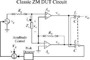
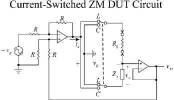
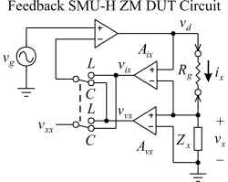
Bridge
type |
V
Divider |
Fb
SMU-H |
SMU-H |
Fb
SMU-H |
TWG |
|
Phase
detector |
zc
cmprs ®
cntr |
PLL
I-Q gen, aSw mpyr |
analog
mpyr, LPF |
aSw
mpyr, LPF |
none |
|
DVM |
2000
cnt μC
Σ-Δ |
12-bit 2-ch ADC |
14-bit
ADC |
12-bit
SA ADC |
14-bit
VFC, μC
Σ-Δ |
|
Power
Supply |
±5
V, 0.2 A 2 W
|
±5 V,
200 mA 2 W |
±5 V,
2.6 A 25 W |
±5 V,
200 mA ±12 V,
250 mA 50 W |
5
V, 400 mA ±12
V, 100 mA 4.4
W |
|
Front-Panel |
±3.3-digit
LED, 4-sw, digiknob, mode LEDs |
±3.3-digit
LED, 4-sw, digiknob, mode LEDs |
16
char LCD, 4-sw, mode LEDs |
16-char
LCD, 4-sw, mode LEDs |
±4-digit
LED, unit
& mode LEDs |
|
Proto μC,
μC |
μDAS,
ATmega8515 |
MC2,
ATmega8515 |
MC2,
PG2A ATmega328 |
Huron,
ATmega8515 |
miniDAS,
ATmega328 |
|
Notes |
Min cost
& analog parts, max μC |
BK875A-derived |
Min
analog, PG2A
pwr SMU-H |
General-purpose
ZM, datalogging |
Wide
L, C range; max
digital; sin-cos gen |
ZA200
Z Analyzers
The Innovatia ZAs are wideband, not narrowband,
instruments. Wideband ZAs do not have as large of a dynamic range, but they are
simpler (fewer parts) and lower in cost.
The ZA201 prototype has functioned in the past but the design is being modified. The ZA202 is in concept phase.
|
ZA200 Series |
ZA201 |
ZA202 |
|
V range, dec |
1 |
2 |
|
V range, fs |
250 mV, 2.5 V |
25 mV, 2.5 V |
|
I range, dec |
3 |
3 |
|
I range, fs |
100 μA, 1 A |
10 μA, 10 mA |
|
ZA Freq range, dec |
3 |
7 |
|
ZA Freq range |
80 Hz, 80 kHz |
80 Hz, 8 MHz |
|
Z, R range, dec |
8 |
5 |
|
Z, R range, fs |
250 mΩ, 25 kΩ |
2.5 Ω, 250 kΩ |
|
L, C range, dec |
8 |
12 |
|
L range, fs |
500 nH, 50 H |
500 nH, 500 H |
|
C range, fs |
100 pF, 10 mF |
1 pF, 1 mF |
|
Bridge type |
Innovatia |
Innovatia |
|
Generator type |
XR2206 |
AD9833 |
|
Phase acq |
cmprs, XOR gate, LPF Þ μC ADC |
aSW mpyr, LPF Þ μC ADC |
|
Magnitude acq |
wideband PGA, sync S&H, μC ADC |
bandpass PGA, |v|, LPF Þ μC ADC |
|
FRA Freq range |
5 Hz, 500 kHz |
1 Hz, 10 MHz |
|
Magnitude inaccuracy |
1 % |
1 % |
|
Phase resolution, deg |
0.5 |
0.5 |
|
Board Configuration |
μC&FP, ZA, PS |
μC&FP, ZA, PS |
|
Front-Panel |
8-char LED, 4-sw |
Graphic
LCD, 4-sw, digiknob |
|
μC |
μM Þ MC56F8025 (M0B) |
MC56F8025 (M0B) |
|
Power Supply |
12 V, 1 A in ±5 V, 1.1 A ±12 V, 50 mA 12 W |
12 V, 0.25 A in ±5 V, 100 mA ±12 V, 50 mA 2.5 W |
|
Development Phase & Notes |
Design (D0) power-circuit applications |
|
Innovatia Assistants inquire.
![]()
![]()
![]()